
Some Assembly Required
Posted: 2015-12-03 Filed under: Workshop, WPF Leave a commentThis post I’ll demonstrate a constructing a meta-model; a model made out of little fragments of 3D models snapped together, scaled and rotated. I’ll follow up with a model painting post. Somehow I have managed to emulate all the tedium and time-consuming nature of painting miniatures for table-top RPGs, and put it into software, while retaining the tedium and time-consuming nature of working with miniatures. It’s actually not that bad since I created a “duplicate miniature” function.
Anyway, within a resource manager, we need to create a new meta-model and base it off a XAML file that has “fragment references” (I use one called RootBase.xaml). Fragment references are a XAML extension I created that indicate where a fragment can be included in a model. The technique is recursive so that fragments themselves can contain fragment references. Think of a fragment reference as a placeholder.
<Model3DGroup xmlns="http://schemas.microsoft.com/winfx/2006/xaml/presentation"

xmlns:uzi="clr-namespace:Uzi.Visualize;assembly=Uzi.Visualize">

<Model3DGroup.Children>

<Model3DCollection>

<uzi:FragmentReference Key="Core" OffsetZ="{uzi:DoubleVal Key=CoreElev,Value=2.1,MinValue=0,MaxValue=5}"/>

</Model3DCollection>

</Model3DGroup.Children>

</Model3DGroup>

just need to pick a model file with fragment references
When we open the meta-model in the editor (built on the Helix Toolkit) we can see that it is empty. Evidence that there is a reference in the file shows in the “Root Node” of the tree-view. There is a single reference called “Core” which is a placeholder (literally, a location reference point about 2.1 feet above {0,0,0}), that can be adjusted in a variety of ways.

haven’t added any fragments yet
Since my resource package already has my collection of fragments included, I only need to assign parts to begin constructing the meta-model. In the following image I’ve assigned “RootLegs.xaml” to the Core reference. This provided two more reference points, one for each leg, which I went ahead and assigned “Leg.xaml” to each. Leg.xaml has a connector reference so we can build downward to another leg part, and then a foot part. It also has a VisualEffectMaterial called “Leg” which is a texture reference to be explained a little more in another post.

I’ve skipped ahead just a little bit
What I also did was Cloned the Core reference so I could get a second fragment anchored to the same spot. When cloning, I have to supply the fragment that will be held in that spot; in this case I chose “Belt.xaml“. Belt has a Buckle reference at the front, and a Stack reference onto which a torso is usually placed.
After a bit more of this, I get pretty close to a complete (unpainted) miniature.

now I’ve skipped ahead a lot
I left the right hand off, so now I assign it.

any part can be added to any reference spot
Knowing the hand is a little bit big, I need to adjust it down. The hand model contained another extension called a DoubleRef, which provides me a way to adjust it in the workshop. Actually, the entire conic mesh is programmatically generated (and cached) via a markup extension as well!
<GeometryModel3D Material="{uzi:VisualEffectMaterial Key=Hand, VisualEffect={uzi:SenseEffectExtension}}"

Geometry="{uzi:ConeMesh CacheKey=1, Origin={uzi:Point3DVal}, Direction={uzi:Vector3DVal Z=-1}, Height={uzi:DoubleVal Key=HandLength,Value=0.4},BaseRadius={uzi:DoubleVal Key=WristRadius,Value=0.18},TopRadius={uzi:DoubleVal Key=FingerRadius,Value=0.12},ThetaDiv={uzi:IntVal Key=HandTheta,Value=8},BaseCap=true,TopCap=true}">

the hand was bigger than the sleeve until I adjusted it
Both the “Doubles” tab and the “Ints” tab control the value of all references to the named integers and doubles in the miniature. ArmTheta, for instance, controls the number of “sides” for an arm cylinder. You can guess what the other ones do.

I have a separate utility to construct head models, I’ll explain that sometime if I get around to it
Next I put a staff in the wizard’s hand. Naturally this doesn’t orient and position neatly into my customized model.

the rest of the miniature had been rotated into place already
So, I select the staff, and adjust the pitch. I had been adjusting the rest of the model to this point in a similar way, and gave the right arm a slight downward pitch, which I have to overcompensate for by applying a 95 instead of a 90 degree pitch.
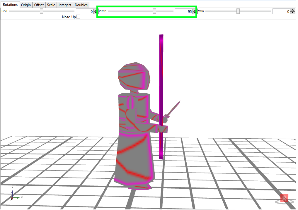
aligned, but too high
Also, the staff is running a little high, so I adjust the Z-Origin up a bit; origins are relative to the fragment reference point for the fragment. Offsets are in “final” model-space and can be more tricky to work with. I also assigned a fragment to the “Focus” reference of the staff fragment.

almost done
I fix this by Rolling the staff fragment 180 degrees, then I adjust the scale of the Ball fragment (since I don’t have separate radius parameters for a sphere mesh).
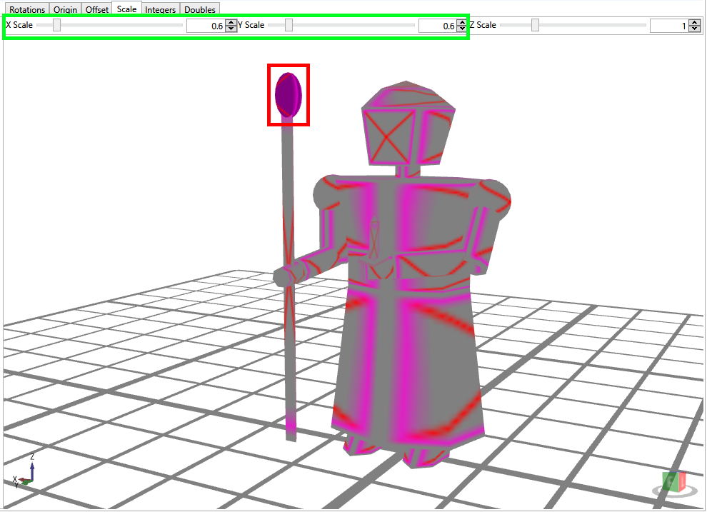
not to scale
Next time (perhaps), painting a miniature.
