
Visualization
The Visualization assembly in the Ikosa framework covers two functional goals. It defines most of the basic geometric capability and structure of the framework, and it provides rendering support in the context of the WPF output model. This rendering support is provided for both “workshop-side” tools, and the client application.
I’ve tried to keep most of the WPF dependencies away from the other game-model assemblies; under the assumption that this could be ported to other presentation models at some point in my indefinite future.
Geometries
OpenGL gaming via the SRD is heavily invested in geometric rules and descriptions that revolve around the 5 foot square (obviously projected onto a flat 2D plane rendered by pen/pencil onto paper; or white-board marker onto whiteboard). Having data structures and code to handle recurrent geometric rule patterns was an early and ongoing priority.
Some of the basic cell-geometric concerns are encapsulated in interface definitions. Cell-location, geometric-size and geometric-region. One reason these are defined as interfaces (rather than say, classes or structures) is that in some higher levels of the gaming framework attempting to maintain a class dependency chain is problematic (the CLR only allows single-chain implementation inheritance, which I agree with is a good thing), and the “sealed” nature of structures would mean writing as much access and glue code to coerce other higher-level usages of structures into the more primitive ones. I’d love to write more about design thinking with object-oriented techniques, but not in this context…
Interfaces
- ICellLocation: a cell location, and a function to return a CellPosition struct
public interface ICellLocation
{
    int Z { get; }
    int Y { get; }
    int X { get; }
    CellPosition ToCellPosition();
}
- IGeometricSize: a geometric size (in both long and double)
public interface IGeometricSize
{
    long ZHeight { get; }
    long YLength { get; }
    long XLength { get; }
    double ZExtent { get; }
    double YExtent { get; }
    double XExtent { get; }
}
- IGeometricRegion: a geometric region (minimally with spanning extents); complex geometry is expected which is why the ContainsCell and IsCellAtSurface functions are defined; being within the Lower/Upper extents does not guarantee containment within the geometry
public interface IGeometricRegion
{
    int LowerZ { get; }
    int LowerY { get; }
    int LowerX { get; }
    int UpperZ { get; }
    int UpperY { get; }
    int UpperX { get; }
    Point3D GetPoint3D();
    IEnumerable<ICellLocation> AllCellLocations();
    bool ContainsCell(ICellLocation location);
    bool ContainsCell(int z, int y, int x);
    IGeometricRegion Move(ICellLocation offset);
    bool IsCellAtSurface(ICellLocation location, AnchorFace surfaceFace);
}
- IGeometryBuilder: used in “higher” gaming mechanics to construct geometries based on spatial targeting information (such as “sphere centered at point” or “cone centered on spell caster”)
public interface IGeometryBuilder
{
    IGeometricRegion BuildGeometry(LocationAimMode aimMode,
                                   ICellLocation location);
}
Primitives
While I have defined and typically use interfaces throughout the API, I recognized the need to have default implementations, thus the following.
- Cell-Position: ICellLocation, IGeometricRegion – a structure, so it can live on the stack
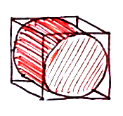
- Cubic: IGeometricRegion, ICellLocation, IGeometricSize – orthogonally cubic cylinder
- Sphere: IGeometricRegion – sphere
- Cone: Sphere – may not be obvious, but game-cones are defined by distance and angular cut, which makes them technically a constrained version of a sphere
- Cylinder: Sphere – merely based on sphere due to some data and implementation conveniences
- Multi-Region: IGeometricRegion – aggregates multiple regions, with capability to exclude other regions
Builders
Builders are capable of building geometries, there is one for each IGeometricRegion defined above. These are defined to help with game-processes (ongoing effects and spells) that need to create geometries. Some effects are mobile, so it also becomes necessary to create geometries multiple times for a given effect (if for instance a spell-caster moves while under an emanation centered on the caster).
Cell Spaces
Cell spaces are the definition of the modeled physical contents of a map cell. The visualization assembly maintains functions to support rendering cell spaces through WPF. Most of the cell-space types are described below.
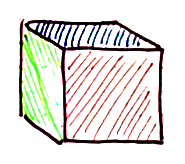
- Uniform: space filling solid, liquid or gas (visible or invisible)
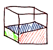
- Sliver: two rectangular cylinders of materials crossing an orthogonal axis
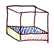
- Slope: like a sliver, but differentially sloped along another orthogonal axis
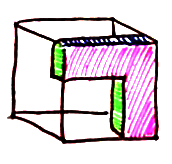
- Wedge/Corner: block hugging a corner or cut-out from a corner (depending on materials)


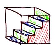
- Stairs: two materials stepwise from corner to opposite corner; two faces completely blocked, two completely open, two partially blocked (depending on materials)
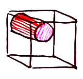
- Cylinder: solid material with a non-solid surrounding running along an orthogonal axis
- Small Cylinder: cylinder taking up about a quarter of a cell, snapped to a corner; using mechanics similar to wedge/corner
- L-Frame: designed for door framing
- Panels: somewhat more flexible multiple side contents and internal structure
Spatial Enums
The Visualize assembly defines a number of enums that are used semantically for such things as spatial relations and key values in dictionaries. A few of the more prominent ones are listed below.
- AnchorFace: cuboid face direction; 6 cardinal cube faces
public enum AnchorFace { XLow, XHigh, YLow, YHigh, ZLow, ZHigh }
- OptionalAnchorFace: same as above, but effectively nullable via None
public enum OptionalAnchorFace { None, XLow, XHigh, YLow, YHigh, ZLow, ZHigh }
- AnchorFaceList: bit for each anchor face; extension methods for manipulation and access as a list-like object. I’ll go into more detail in “optimizations” later.
[Flags]
public enum AnchorFaceList : byte
{
    None = 0,
    XLow = 1,
    XHigh = 2,
    YLow = 4,
    YHigh = 8,
    ZLow = 0x10,
    ZHigh = 0x20,
    All = 0x3F,
    LowMask = XLow | YLow | ZLow,
    HighMask = XHigh | YHigh | ZHigh,
    ZMask = ZLow | ZHigh,
    YMask = YLow | YHigh,
    XMask = XLow | XHigh,
    XYMask = XMask | YMask,
    YZMask = YMask | ZMask,
    ZXMask = ZMask | XMask
}
- Axis: orthogonal and parallel information
public enum Axis : byte { X = 0, Y = 1, Z = 2 }
- LocationAimMode:
public enum LocationAimMode
{
    None = 0,
    Intersection = 1,
    Cell = 2,
    Any = 3
}
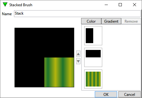
Brushes/Materials
Brushes (and Material3D instances based on those brushes) provide texture both figuratively and literally to the game visualization. Brushes and materials are projected during load time through pixel-shaders to get a pre-cached set of gradients and visual patterns matching light and vision expectations of characters (such as low-light vision, dark-vision and blind-sight).
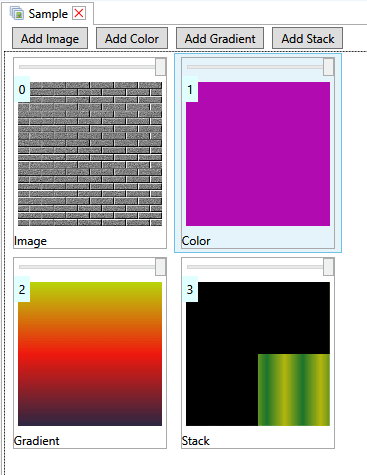
- Images: imported images
- Colors: solid colors
- Gradients: transitions in colors across the brush tile
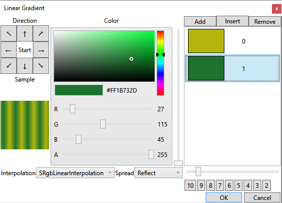
- Brush Stacks: allows stacking multiple gradients with transparencies to construct complex patterns
Brush Sets
Multiple sets of brushes can be stored in a resource manager, and a single brush set can be defined for each model as needed. Resource brush-sets are used when defining cell-space and panel textures. Brush-sets for models define that textures available to customize a model.
Icons
“Icons” are small 2D line-work XAML-based images intended to represent items within menus and lists. Each item class has an item key (string) defined that is used to reference an icon available via the map’s resource manager. Each item instance may override the class item key with a specific item key, but if it is not resolvable to an actual icon file, it will fall back to the class icon key.
Icons are defined on a WPF Canvas element with fixed dimensions of 96 x 96 WPF units and a very magenta background. Typically I use KaXaml to edit and preview the icons and have a tendency to do a lot of copy and modify to simplify my life and maintain a consistent design aesthetic.
A utility I built (whose functions I should probably integrate into the workshop) prepares the XAML files by nulling the canvas background so it is transparent, and wrapping the content in a WPF DataTemplate. This is done with XML processing instead of XAML processing so that markup extensions are not expanded inadvertently. The final XAML file generated is what I import into a package as an icon resource.
Sample Processed XAML: guisarme
<DataTemplate xmlns="http://schemas.microsoft.com/winfx/2006/xaml/presentation"
    xmlns:x="http://schemas.microsoft.com/winfx/2006/xaml">
 <uv:ResourceContent
    xmlns:uv="clr-namespace:Uzi.Visualize;assembly=Uzi.Visualize"
    ResourceDictionary="{DynamicResource dictStyles}">
  <Canvas Background="{x:Null}" Tag="R" Width="96" Height="96"
    xmlns="http://schemas.microsoft.com/winfx/2006/xaml/presentation"
    xmlns:x="http://schemas.microsoft.com/winfx/2006/xaml">
   <Path
Data="M47,27A4,8,0,0,1,47,11A2,2,0,0,0,43,11A4,4,0,0,1,51,11A2,9,180,0,1,50,28z"
Stroke="#FF000000" StrokeLineJoin="Bevel">
    <Path.Fill>
     <RadialGradientBrush Center="0.2,0.6">
      <RadialGradientBrush.GradientStops>
       <GradientStop Color="#FFD0D0D0" Offset="0" />
       <GradientStop Color="#FF707070" Offset="1" />
      </RadialGradientBrush.GradientStops>
     </RadialGradientBrush>
    </Path.Fill>
   </Path>
   <Rectangle Fill="#FFD2B48C" Stroke="#FF000000" Width="4" Height="68"
      Canvas.Left="46" Canvas.Top="25" />
   <Rectangle Fill="#FFC0C0C0" Stroke="#FF000000" Width="4" Height="8"
      Canvas.Left="46" Canvas.Top="25" />
   <Rectangle Stroke="#FF000000" Width="4" Height="14"
      Canvas.Left="46" Canvas.Top="80">
    <Rectangle.Fill>
     <LinearGradientBrush StartPoint="0,0.5" EndPoint="1,0.5">
      <LinearGradientBrush.GradientStops>
       <GradientStop Color="#FFA52A2A" Offset="0" />
       <GradientStop Color="#FFD2B48C" Offset="0.5" />
       <GradientStop Color="#FFA52A2A" Offset="1" />
      </LinearGradientBrush.GradientStops>
     </LinearGradientBrush>
    </Rectangle.Fill>
   </Rectangle>
  </Canvas>
 </uv:ResourceContent>
</DataTemplate>
Sample Icon: Guisarme

Models
Models represent actors and non-item objects in the system as presented in a view of the game-world. As with many elements of the Ikosa framework, the modeling system has grown and changed over time and now contains two main types of model structures. All models are effectively WPF Model3D instances when they get fully constructed by the visualization system.
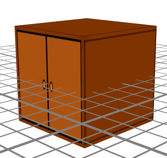
“Single”-piece models were the first model system and are for when the geometry of a model is specified in a single model resource stream. Materials (textures) can be defined via markup extensions which reference a set of brushes local to the model in the package. Additionally, there is limited parameter support via markup extensions that can be used in rotational and translational transforms so that things like cabinet doors and drawers can be implemented.
Parameters should be generally integral as they are used (along with shadings) to hint at cacheable copies of models. Parameters in single-piece models are provided by the game-system at runtime and typically represent object state such as “open” and “closed” that can map onto cabinet doors and bureau drawers.
I have a standalone utility that I use to generate most of the models (via XML) I use for furniture, as it is important to maintain markup extensions that represent particular “sides” to the furniture so they can be shaded appropriately based on lighting and vision.
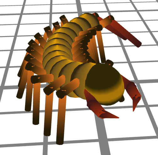
Meta-models are the “newer” model system and are particularly useful for constructing new models (specifically character models) in the workshop UI. A meta-model is composed of fragments that contain both geometry and connection points to which additional fragment references can be attached. The network of fragment references is tracked and maintained and includes relative displacements, rotations and scales as defined. Additionally, parameters can be declared in the fragments and are expressed in the workshop UI for manipulation and persistence in the network structure. Parameters can be global. or locally overridden per fragment reference and are typically used to scale parts of the geometry and connection point offsets. Brushes can also be declared globally and locally overridden per fragment reference.
I have posted blog entries on the meta-model structuring and texturizing customization systems in my general blog. Hopefully looking at how they are used might help understand the system. With the system, it is possible to create the centipede with only a handful of fragments referenced multiple times and brushes referenced globally with a few overrides, and then tweaking some rotations here and there.
Markup Extensions
WPF Markup Extensions get processed during XAML Load and converted into whatever value the markup is attributed to provide. I’ve defined (at least) three types of extensions: parameter calculation, injection and cross-referencing, Point3D/Vector3D value providers and 3D mesh generators.
Parameter Calculation, Injection and Cross-Referencing
- Value: integer and double-precision (with default and ranges)
{uzi:DoubleVal Key=TorsoThick,Value=0.84, MinValue=0.2, MaxValue=1.4}
- Sum: integer and double-precision (referencing a previously defined DoubleVal).
{uzi:DoubleSum A={uzi:DoubleVal Key=Arm2Length}, B=-0.09}
- Product: integer and double-precision (referencing a previously defined DoubleVal).
{uzi:DoubleProduct A=0.725,B={uzi:DoubleVal Key=TorsoThick}}
Point3D/Vector3D Value Providers
- Point3D: typically used in 3D Mesh generators so they can be parameterized (origin: 0,0,0)
Origin={uzi:Point3DVal}
- Vector3D: typically used in 3D Mesh generators so they can be parameterized
3D Mesh Generators
These are mesh generation for basic 3d solids and can be used in XAML markup as the geometry for a GeometryModel3D:
- Cone
{uzi:ConeMesh CacheKey=1, Origin={uzi:Point3DVal},
              Direction={uzi:Vector3DVal Y=1},
              Height={uzi:DoubleVal Key=Hand.Length,Value=0.4},
              BaseRadius={uzi:DoubleVal Key=Wrist.Radius,Value=0.18},
              TopRadius={uzi:DoubleVal Key=Finger.Radius,Value=0.12},
              ThetaDiv={uzi:IntVal Key=Hand.Theta,Value=8},
              BaseCap=true,TopCap=true}
- Cylinder
{uzi:CylinderMesh CacheKey=1,
                  P1={uzi:Point3DVal
                         Z={uzi:DoubleSum
                               A={uzi:DoubleProduct
                                     A={uzi:DoubleVal
                                           Key=ArmLength,Value=0.75},
                                     B=-1},
                               B=-0.09}},
                  P2={uzi:Point3DVal
                         Z={uzi:DoubleProduct
                               A={uzi:DoubleVal
                                     Key=ArmDiameter,Value=0.4},
                               B=0.4}},
                  Diameter={uzi:DoubleVal Key=ArmDiameter},
                  ThetaDiv={uzi:IntVal
                               Key=ArmTheta,Value=9, MinValue=5, MaxValue=16},
                  BaseCap=true,
                  TopCap=true}
- Sphere
{uzi:SphereMesh CacheKey=1, Radius={uzi:DoubleVal Key=JointRadius,Value=0.25}}
- Elliptical Tube: used for bows mostly
{uzi:EllipticalTubeMesh CacheKey=1,
                        PolarAxis={uzi:Vector3DVal X=-1},
                        Center={uzi:Point3DVal Y=-0.75},
                        PrimaryAngle=90,
                        AngularSpread=120,
                        LateralRadius=2,
                        PrimaryRadius=0.75,
                        LateralTubeThickness=0.025,
                        PrimaryTubeThickness=0.1,
                        CurveSegments=8,
                        ThetaDiv=5}

[…] Visualization Overview section is now available in my growing tuning series. I struggled with being somewhere between a […]